Building an FTIR Multi-Touch Pad from Scratch
Disclaimer: We built this cute little multi-touch pad based on instructions by Anne Roudaut and her colleagues to be found on this website. Here I merely provide some additional detail that will help me to remember what we did and may help others who would like to build this device.
1: Consult the original website and buy your materials:
I bought most of the material as outlined in the original shopping list, except for some hardware we already had at home. Visit this website for the shopping list. Specifically I purchased:
- 4mm acrylic and had it cut to the measurements given in the shopping list. I think something smaller would have also sufficed in the end because my camera cannot cover the whole area of the pad.
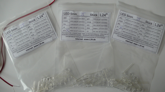
- Green, red, and white LEDs as indicated on the shopping list
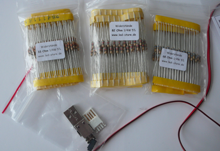
- Resistors as indicated on the shopping list. Make sure they are useful for the LEDs you have
- Everything to make a USB cable
- Paper holder plastic (for a lack of a better name)
- Silicone spray - I am not quite sure what to use this for, yet. I tested it on some plastic foil that I put on the pad but that hasn't brought any benefits. I am not sure if spraying the acrylic is a good idea - comments are welcome.
| 
|
| Resistors and USB cable material | The three different colors of LEDs I bought |
2: Make the USB cable
This is easy. Just assemble the pieces you have. The only difficult part is getting the colors to the pins right. Red goes in Pin 1, black (ground) in Pin 2:
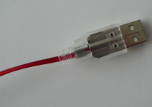
The assembled USB cable should look like this
3: Prepare the Bending of the Acrylic
First remove the plastic that should cover the acrylic on both sides. In the picture below the plastic is still on. The acrylic should not be green like there, it should be really clear.
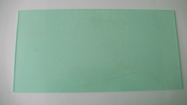
The acrylic with the plastic still on. Remove it next.
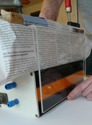
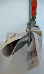
In order to get really straight edges we built a little device to aid in the bending process. It consists of two boxes high enough so that the bent edge does not reach the table surface. Then the acrylic on the box and some wood on top screwed together so we won't get a bulge when we bend. Then we wrapped this whole thing in newspaper so the acrylic won't scratch.
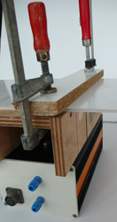 | 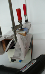 |
| The bending setup we used | The final pre-bending state |
Then fire-up your heatgun. We started out very carefully with about 170C but quickly settled on 280C which worked well. It took about 2-3mins of heating the bending edge from top and bottom before we could easily bend the acrylic.
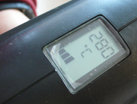
Temperature we used for the heatgun
Hold the acrylic in place for a little bit while it is cooling. Otherwise it will move back out. Once you are done beding both sides remove the lower box and let the acrylic cool standing up.
 |  |
| Hold the side in a bit while it's cooling | Let it cool standing up once the second side is bent |
4: Build the LED light-strip
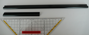
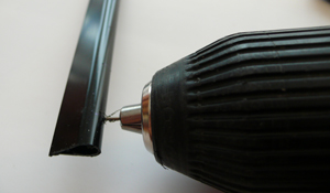
First I cut the paper holder clip into a length that would fit the width of my multi-touch pad (about 7cm)
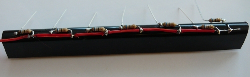
Then I used a tiny drill to make 7 pairs of holes for the 7 LEDs.
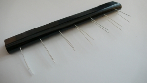
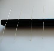
Next I stuck all the LEDs in the order I wanted into these 7 holes. It's important that all the long ends are on one side and all the short ones on the other.
 |  |
Check Anne Roudaut's website for how to calculate which LEDs to put where and which resistors to pick for connecting them.
So I assume you know which resistors you want. Next start to solder them on.
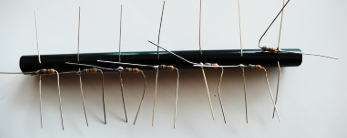
Soldering on the resistors. This is for only white LEDs
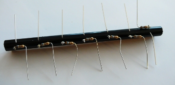
Next cut off the unnecessary wire next to the soldering points
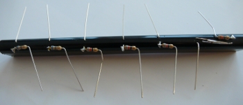
An alternative where two red LEDs on the right are connected in series (like in the original example)
(Btw, the most beautiful solderings have been done by my Dad who learned how to do this professionally. The ugly ones are probably mine... )
Next prepare the USB wire so you can solder it on and connect the LEDs. To do so you first have to rip it apart a little - just do this for the length of the LED strips:
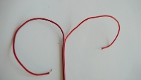 | 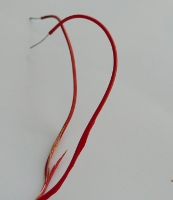 |
| Like this | Not like this |
Next you solder on the wire. This is a little tricky because you first have to melt away a little of the insulation in the right spot (I used the soldering iron for that) and then you can solder the cable on as intended. Finally this should look like so:
One side of the wire soldered on
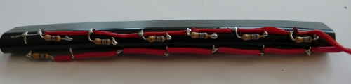
The second side with all remaining wire from the LEDs cut off
Almost Done!
Now comes the exciting moment where you stick the USB cable into your PC or other USB power source to see if your calculations and solderings worked out ok. For our colored LED strip it then looked like this:
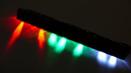
And it works
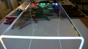
And this is what it looks like on the acrylic
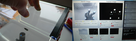
Software Calibration
Now comes the really tricky part. We want to do something with the device. I stuck my camera underneath and connected CCV - depending on your camera this can work more or less well. This image shows that this solution does indeed work and you can track fingers. BUT: it's very light sensitive (don't turn on overhead lights). Also note that my camera isn't able to track the whole multi-touch pad we built. The pad is way too big so I can only track input in a small area of the touchpad. This is not very good for practical purposes and the solution would be to either build a smaller pad or to buy a camera that has a wider field of view.
The next difficulty is to calibrate the input. This is tricky because we don't in fact project onto the touchpad, so the typical CCV calibration does not work. What I did is to build a small paper calibration device with calibration points on it. I cut these out and use my finger through the holes to calibrate using the standard CCV method. This works reasonably well. I'll upload a picture of this soon...